
As a structural engineer, we also are asked to review the ETABS Model especially once you are the senior or head of the department or as a 3rd party checker. this is often to make sure that the planning shall meet all the relevant standards for safety, durability, and serviceability before submitting for authority approval.
This article aims to offer you the overall idea of the essential Parameter checks and basic requirements that must be considered in reviewing an ETABS model.
-
Check for, Maximum Displacement in etabs
- Go to the Display tab menu
- Select Story Response Plot
- Select maximum Story displacement from the display type
- Select EQx from the Load case and Check the maximum value
- If it is within the Limit then its ok
- Again select EQy and Check the maximum Value if it’s in the limit then okay.
- Formula to check Max displacement=Building total height X 0.004 (from code)X1000 mm

-
Check for, Maximum Drifts in etabs (IS 1893 part 1 ,peg28, Clause 7.11.1.1)
- Go to the Display tab menu
- Select Story Response Plot
- Select maximum Drift from the display type
- Select EQx from the Load case and Check the maximum value
- If it is within Limit then it’s ok
- Again select EQy and Check the maximum Value if it’s in the limit then okay.
- Formula to check Max drift=0.004 mm

Note: If our Result Exceed maximum Limit Then Change (increase) Section Property of Beam or Column then Check again using same method.
-
Check for, Model Participating Mass Ratio in etabs
- Go to the Display tab menu
- Click on Show Table
- Select Analysis Result
- Select Structure output and expand
- Select Model information and expand
- Select the Model participating mass ratio
- Click on OK,Now you have seen the table check :
- We Need to Check the time period, UX, UY, and SumUX (I.e. modal mass prt. Ratio) on the 12th

-
Check for Sum UX (Modal Participating mass ratio)
-It should be always greater than 95% (ie. Value should be above 95) in 12th mode.
-
Check for Time period
-It should be a Normal value that is if it is shown in 0.00X value it is not Valid it is abnormal.
-
Check for UX & UY (to avoid torsion)
–We need to check Mode1 and Mode2 Value in Criss-Cross, If any one group of them crosses 40% Value in any one then it’s Ok.

-
Check for, Center of Mass Rigidity XCR & YCR Value
- Go to the Display tab menu
- Click on Show Table
- Select Analysis Result
- Select Structure Result
- Check the Center of Mass of Rigidity Under Other Output Items
- OK

Here there is Not Calculated XCR & YCR Value initially in ETABS so we need to calculated it manually, For this:
- First Unlock your Model
- Go to analyze tab menu
- Select set load case to run
- Check for Calculate diaphragm Center of rigidity
- Click on Run Now Bottom
- Wait for 100% to finish.
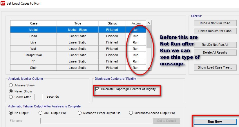
- Now again Run analysis model.
- And Check Center of Mass of Rigidity (XCR & YCR) Under Other Output Items.
- If those Values not Exceed 5% in each Story then it’s OK.

-
Check for Torsional Irregularity
According to IS Standard the ratio of Max displacement and average displacement should be less than 1.2.
$max < 1.2$avg ————–No irregularity
1.2$avg <= $max <= 1.4 $avg ————–Irregularity
$max > 1.4 $avg —————— Extreme Irregularity
- Go to Plan View and Select Top Story Plan
- Go to the Display Tab menu
- Select Deformed Shape
-Check Torsion in EQx Direction
- Select EQx load case
- Click any Joints and Calculate it for EQx Direction ( ie. Select joints in Y –Y-direction on tabs to get Value)
-(Avg Displacement = (11.275 +10.917)/2 = 11.096 mm =$avg
where, Max . Displace ment $max = 11.275 mm )
-Check, 11.275/11.096 = 1.016 <1.2 ———–( the model is not irregular in EQx)
$ max < 1.2 $ avg —– it is Safe
-Check in EQy Direction too.
- Select EQy load case
- Click any Joints and Calculate it for EQx Direction( ie. Y Select joints in X –direction on etabs to get Value)


NOTE : IF EACH CRITERIA ARE PASSED THEN START TO DESIGN








Keep up the fantastic work!