
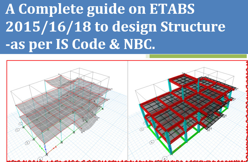
Etabs tutorial includes a complete package of Structural analysis of Structure using IS code and NBC code ,Starting with Following Course Content Like,Units,Section Database, Design Code selection, Grids & Define material properties accurately.
Contents:
- Grid and story data
- Defining and assigning beams
- Defining and assigning columns
and dividing the frame line
- Defining and assigning slabs
– Dividing the selected shells
– Defining slabs between irregular frames
– Assigning staircase
– Offset option for line elements
– Assigning cantilever slab
-Mirror option for elements
-Chamfer slab corners
- Adding and replicating a new story
– Selecting the single story elements
– Visibility options for story elements
– Reassigning the section property
- Defining and assigning retaining wall
– Assigning opening between frames
- Model view options
– Extrude option for frames and shells
– 3-D model rendering
Building Design – Stepwise
- Example: Analysis & design a following Building (plan) Using per IS –codes using ETABS Software.
No. of storey: 4 storey: 3 m ht up to 3rd floor & 2.5 m ht on roof terrace For staircase covering only.

| Length (L) | A | B | C | D | E | F | G | H | I | J | K | L | M | N |
| 0 | 1.2 | 2.7 | 3.9 | 4.5 | 5.8 | 6.7 | 7.6 | 8.8 | 12.6 | 16.4 | 17.49 | 18.13 | 19 | |
| Width (B) | 1 | 2 | 3 | 4 | 5 | Grid No. | ||||||||
| 0 | 5.7 | 9 | 11.5 | 13.5 | Distance | |||||||||
MODELING
Step 1:
- Enter grid & Storey data
Step 2:
- Defining & Assigning beams
Step 3:
- Defining & Assigning columns
- Orientation Change of columns (local axis)
- Merging & Dividing the frame line
Step 4:
- Defining & Assigning slabs
- Dividing the select shells
- Defining slab between irregular frame
- Assigning staircase
- Offset option for line elements
- Assigning cantilever slabs ( sunshade/ Chajja)
- Mirror option for elements
- Chamfer slab corners
Step 5:
Adding & replicating a new storey
- Selecting the single storey elements
- Visibility option for storey elements
- Reassigning the section property
Step 6:
Defining & assigning retaining wall /Shear walls
- Assigning opening between frames
Step 7:
Model View option
- Extrude option for frames & shells
- 3D model rendering
Step wise Modeling
Step:1 : Entry grid & Storey data
- Open Etabs application on PC
- Click File
- New model
(model initialization) - Use Built in setting with
- Display unit : metric SI (if you need to model using feet ,inch choose us. Defult and you can change unit later if u want from here)
- Steel Section database: Indian
- Steel Design code : IS-800-2007
- Concrete design code: IS-456-2000.
- Open new model quick templates.
- Choose Custom grid Spacing in Grid dimension (too unlink spacing height wise)
- Choose Custom Storey data in storey dimension.
- Choose Add structural object (Grid only).
- OK
- Go to Edit Menu
- Edit Storey and grid system data.
- Add new grid system data.
- Modify / show grid system.
- X-Grid data
- Click Grid ID & Add for node (A to N)
- Click X-coordinate & double click & Edit (Length wise)
- Y-Grid data
- Same as X-grid data input as drawing
- Ok
- Delete previous gird & Select new
- To Input storey Data ( As per Section drawing),
- Modify / Show storey data
- Edit storey name (1st, 2nd,3rd,…,Top: check height elevation for this)
| Storey | Height |
Elevation |
Master Storey | Similar | S plane | ||
| Storey 2 | 3 | 6.45 | No | P-Storey | |||
| Storey 1 | 3 | 3.45 | No | P-Storey | |||
| P-Storey | 0.45 | 0.45 | Yes | None | |||
| Base | 0 |
- OK
- Ok
- To view on 3D
- Go & Click 3D view
Step:2 : Defining & Assigning Materials on Member/ beams
Defining Material:
- Go to define Tab
- Material Property
- Add new material
- Region : Nepal/ India
- Material Type : Concrete
- Standard: Indian
- Grade : M20 (i.e. for Slab & Beam)
- OK
- Material Property data
- Material Name : M20
- Ok
Again,
- Add new material
- Region : Nepal/ India
- Material Type : Concrete
- Standard: Indian
- Grade : M25 for Column
- OK
- Material Property data
- Material Name : M25
- Ok
Assign Material:
Note: (Before Assign material go to Plan view)
- Go to plan view
- Select plan view ( now we are planning to draw my beam in P-storey so, select P-storey by cursor; i.e. my master plan)
- Select: P-storey
- Ok
To drawing beams, first define beam
- Go to define ( to drawing beams)
- Section properties
- Frame Sections
- Add new property
- Select type : Concrete
- Beam name in property name : B240X500
- Material: M20
- Under Section dimension:
- Depth: 500 mm
- Width: 240 mm
- Select property/ Modifier
- Change torsion constant 1 to 01
- Moment of Inertia 2 axis : 0.03
- Moment of Inertia 3 axis : 0.25
- Ok
Reinforcement (modify/ show rebar)
- Design type
- Check on M3 design only (beam) for Beam
- Define Cover
- Top bar : 25 mm
- Bottom bar:25 mm
- Ok
Similarly, Add new property for other beam also
- Before assigning beam
- Change one storey to similar storey from bottom tab
(note: except base all the floor are same so select similar storey)
i.e. Same beam will be replicate on storey 1,2,3,.. etc
For drawing beam
- Go to left tab of screen
- Select draw beam /column break icon
- Close property menu.
- Start drawing a beam manually as per grid
- Go To view tab menu
- Set grid system visibility
- Show-3D
Step:3: Defining & Assigning Materials on Column
Defining Material:
- Go to define Tab
- Section Property
- Frame section
- Add new property
- Choose rectangular under Concrete type
- Input data
- Property name : C 240X400
- Material : M25
- Depth=400 mm
- Width=240 mm
- Go to property modifiers (right side) to modify property
- Change torsional constant from 1 to 0.01
- MOI about 2 axis : 0.7
- MOI about 3 axis: 0.7
- Ok
- Click modify /show rebar (under reinforcement ;right side)
- Design type
- P M2-M3 Design (Column)
- Ok
- Ok
- Select assign column
- ok
Assign Material on column:
(Before Assign material go to Icon)
- Select Up arrow and click for top stories
- Change to all stories from bottom layer
- Go to Left side menu
- Click quick draw column Icon
- Close & start assign manually
- Go to 3D view to see.
- Go to Plan View ( note: But in actual plan orientation of column is not similar direction)
- First select the Column which you want to rotate 90 degree for multiple section press CTRL.
- Go to plan view in all stories node
For vertical column, left side
- Go to Assign
- Frame
- Select local axis
- Define orientation
- Angle : 90
- Apply
- Ok
For Inclined column, right side
- Go to Assign
- Clear display of assign
- First, Go to draw beam icon from left menu
- Draw
- Select those column to change
- Assign
- Frame
- Local axes
- Angle : 79.1
- Apply
- Ok
Now Split beams & Column at joint:
- Select entire drawing
- Selecting joint in which we want to split the beam (i.e selecting all column & joint and deselect the point if you don’t want to split).
- Click up & down arrow icon on main tab
- Go to break at intersection with selected frame & joints
- Apply
- Ok
To merge two beam.
- select the beam that you need to merge
- Click join frame icon (near divide frame icon on top tab)







Hey, thanks for the article. Awesome.